Weis Aquires UPF’s Foam Trailer Series
Weis Acquires UPF Foam Trailer Series Weis is proud to announce the acquisition of UPF United Plastic Fabricating, Inc.’s Protector Foam Trailer products. This allows Weis
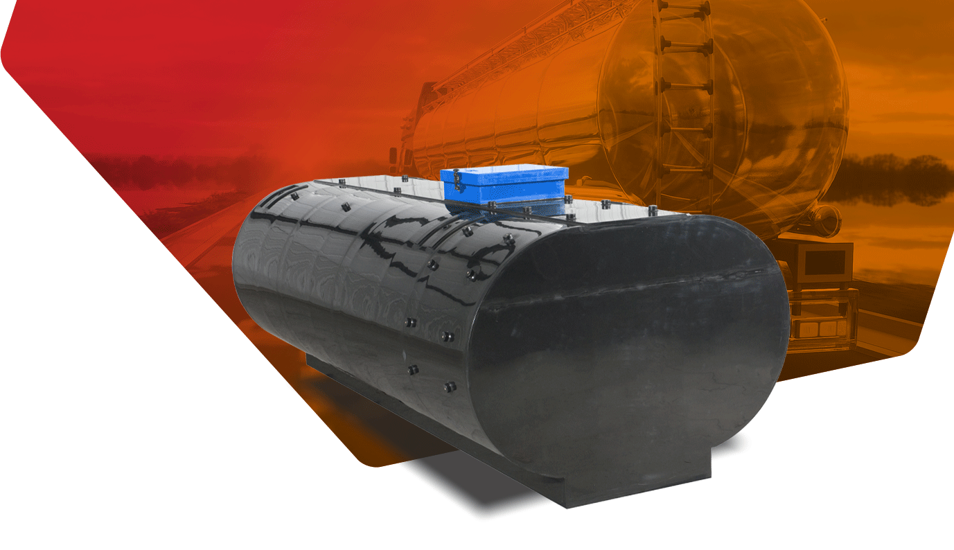
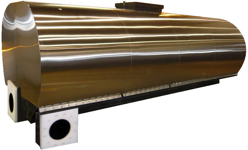
The Ellip-T™ fire fighting tank by UPF range from 1,000 to 5,000 gallons. Lighter than stainless steel or fiberglass, these poly fire tanks are the strongest non-metallic elliptical tanks available. In addition, each tank is non-corrosive, and we manufacture each poly fire fighting tank from UPF’s exclusive PT3™ plastic resin. Introduced to the fire industry over twenty years ago, the UPF elliptical tank immediately became the best-selling elliptical fire fighting tank in the industry. Design tested and field-proven, the Ellip-T™ fire fighting tank is a reliable solution to your water supply needs. This maintenance-free tank is available unpainted, or with provisions allowing the tank to be wrapped with a stainless steel jacket.
Offering various options, the UPF Ellip-T fire fighting tank can be designed to meet your department’s operational procedures. For example, dumps may be rear, side-mounted, or both. You can locate side-mounted dumps at the front, mid, or rear of the tank. Optional foam poly fire tanks or rear storage compartments are also available, along with dozens of other options. Each Elllip-T tank features the Poly-Tank® warranty and the exclusive Closed Curve™ baffle system that meets all applicable NFPA standards. In addition, each of UPF’s facilities is ISO 9001 certified for quality, assuring a lifetime of reliable service.
Ellip T Poly Fire Fighting Tank
The Ellip-T Poly-Tank® shall be manufactured by United Plastic Fabricating Inc. and have a rated capacity of ________ U.S. gallons/liters. It shall be designed in accordance to the appropriate NFPA standard that is applicable for the intended function of the completed apparatus. The purchaser shall specify the type of vehicle that the tank shall be installed in. Ex: WILDLAND, STRUCTURAL PUMPER, RESCUE PUMPER, or TANKER. etc. The tank shall meet or exceed all NPFA guidelines in effect at the time of manufacture. Unlike traditional elliptical tanks, the base of the tank shall be part of the total water storage capacity thus providing a lower center of gravity for the tank when full. The top of the tank shall have a flat, level surface of approximately 18” extending the entire length of the tank to provide safe access to the fill tower.
The tank barrel shall have a large “true” radius, similar in shape to an elliptical type tank (It is recommended that the tank be painted or wrapped to reduce the effects of UV light over long periods of exposure.) All weld seams of the tank shall be trimmed flush to the tanks surface therefore allowing the tank to be painted (with minor preparation) or to accept a stainless-steel jacket. If the tank is to be painted, a special paint process is required for proper adhesion. Contact UPF for this process.
If a stainless-steel jacket is required the OPTIONAL preparation must be specified (see options) so the correct attaching features for the jacket are included on the tank.
MANUFACTURER ISO CERTIFICATION
The tank must be designed and fabricated by a tank manufacturer that is ISO 9001 certified in any of its locations. The ISO certification must be to the current standard in effect at the time of the design and fabrication of the tank.
DESIGN APPROVAL
Each tank is designed to the customer’s specification and/or drawing submittal. An approval drawing shall be provided to the customer before the tank is released to manufacturing. Upon receipt of the signed approval drawing, the tank is scheduled for production. It is the apparatus manufacturers responsibility to ensure the final tank design meets the NFPA requirements for the completed vehicle.
CONSTRUCTION
The Ellip-T Poly-Tank® water (water/ foam tank) shall be of a specific configuration and designed to be completely independent of the body and compartments unless otherwise specified by the purchaser.
The tank shall be constructed using various components made from a high impact polypropylene material. This material, identified as PT3™, shall be a non-corrosive, stress relieved, hi-impact resistant thermoplastic that shall be UV stabilized for maximum protection. Tank shell material thickness shall be determined by the tank’s capacity and shape and may vary from 3/8” to 1-1/2” depending on the tank’s application.
The top of the tank is to be fitted with a removable lifting assembly designed to facilitate tank removal from the vehicle while the tank is empty and all attached accessories are removed.
The transverse and longitudinal swash partitions shall be manufactured from a minimum of 3/8″ thick sheet. All partitions shall be equipped with vent and air holes sized and located to permit air and water movement between compartments. The partitions shall be designed to provide maximum water flow within the tank while meeting the minimum requirements of the applicable NFPA standard for quantity, effectiveness and spacing. All swash partitions interlock with one another and are completely fused to the walls of the tank. Tolerances in design allow for a maximum variation of 1/8” on all dimensions.
All joints shall be fused by a hot air, extrusion type process. All external weld joints shall be leak-tested using a spark type tester with the tank filled to its capacity.
A permanent tank-specific serial number shall be etched onto the inside surface one of the fill tower walls so it is easily visible with the lid open. The height of the etched serial number shall be a minimum of .50”.
SUCTION, FILL AND OUTLET PORTS
If specified the tank shall have one outlet connection to supply water to the pump. The tank-to-pump suction port shall be sized to provide adequate water flow to the pump per the applicable NFPA guideline minimum flow rate. If it is required that the internal tank plumbing draw from the sump, it must be specified by the purchaser.
If specified, a tank fill connection shall be provided and sized to achieve NFPA’s minimum required fill rate for the tank’s application. All tank fill couplings shall be backed with flow diffusers to break up the stream of water entering the tank. They shall also be capable of withstanding sustained fill rates of up to 1000 G.P.M.
The addition of multiple suctions ports, additional fills, dump valve ports, gauge ports and through-the-tank sleeves to accommodate rear discharge piping must be specified by the purchaser as required. All auxiliary inlets and outlets must meet all NFPA guidelines in effect at the time of manufacture.
WATER FILL TOWER
A readily accessible covered fill opening designed to reduce spilling and to allow for manual filling shall be provided on the top of the tank. The minimum size of the tower shall be determined by the tanks fill rate and vent pipe size. It shall be located in a central position along the centerline of the tank cover for minimum spillage while driving. A hinged cover shall be provided on the tower with the hinge located on the passenger’s side allowing easy access from either front or rear for inspection or manual overhead filling. A pin and socket type cover hold down shall be provided to keep the lid securely closed and to provide a safety relief should elevated internal pressures occur during rapid filling. A removable screen constructed of ¼” thick perforated polypropylene shall be provided within the tower. The screen shall have a handle for easy removal. A ledge inside the tower shall be provided to support the screen.
VENTING / OVERFLOW
The tank shall be designed with a 6” ID (unless otherwise specified) schedule 40 polypropylene vent-overflow pipe. This pipe assembly shall run through the tank and shall discharge excess water to a location in the tank floor behind the rear axle so as not to interfere with rear tire traction. This pipe shall also provide venting for the tank during filling and evacuation operations.
COVERS
A single tank cover, approximately 18” wide, shall be provided at the top center of the tank and shall be a minimum of ¾” thick. The cover shall be welded to the tank walls and longitudinal swash partitions for maximum integrity. If required hold down points strategically located in the cover for the tank’s performance. In addition, a minimum of four hold-down/lifting points shall be provided to accommodate the necessary lifting hardware.
SUMP
A plate style sump shall be provided and located in the tank floor to provide a low point to drain the tank. The sump may or may not be located in close proximity to the internal tank suction pipe inlet. The ability to clean out the sump shall be provided thru a bottom-facing threaded connection port with a minimum size of 3” FNPT unless otherwise specified. This port allows for the installation of an NPT plug. This port shall be used as a combination clean-out and drain.
MOUNTING
The tank shall be properly supported, isolated and restrained in all directions. It shall be completely removable for servicing the tank or chassis without disturbing or dismantling the apparatus structure.
The floor of the tank shall be supported by a series of cross members adequately sized to support the weight of the tank, water, foam and if applicable, the hose bed floor and hose. This support structure shall be configured such that the maximum unsupported floor area does not exceed 400 square inches. The tank must be isolated from the support structure by arranging rubber strips under the tank floor to form a grid pattern. This rubber shall have a hardness of 50-70 durometer, Shore A scale. The rubber must be properly attached so it will remain in place during the normal operation of the vehicle.
A picture-frame style support cradle is recommended to laterally restrain the tank. It shall be constructed from a minimum of 2″ x 2″ x 1/4” angle of either mild steel, stainless steel, or aluminum material and shall be properly secured to the vehicle. An alternate method of lateral restraint shall be in form of four corner angles having a minimum dimension of 4″ x 4″ x 1/4” by 6” tall. These corner stops must be properly attached to the subframe.
Although the tank is intended to be “free-floating” to accommodate the normal movements of the vehicle chassis, it is required that there be adequate vertical hold-down restraints to minimize vertical movement during vehicle operation.
To achieve this the tank includes the correct number of internal attaching points, external brackets, and hardware to adequately retain the tank based on the total gallonage of the tank. These “hat” shaped brackets are sized to properly interface with a 1-1/2” square tube welded flush to the tank support cross members.
CAPACITY CERTIFICATION
A certificate of capacity for the water and foam tank(s), if applicable, shall be provided. The volume of water and foam to be contained within the tank shall be verified by using a 3D CAD modeling method of interior displacement thru mass properties or by using a certified test scale.
CENTER OF GRAVITY
A center of gravity calculation that is dimensionally identified on an outline drawing of the tank shall be created. It shall be provided to the apparatus manufacturer with the necessary data to design and certify the apparatus for the NFPA requirements regarding weight distribution and rollover stability. The apparatus manufacturer may use this information to assist in the calculation of the apparatus’s ability to meet the tilt table static rollover threshold or calculated Center of Gravity requirements per NFPA. A center of gravity and weight calculation for both empty and full conditions shall be provided with each tank.
___________________________________________________________________________
OPTIONAL STAINLESS JACKET PREPARATION (JACKET NOT INCLUDED)
The tank shall include wrap attaching bolt strips running along the length of the tank on each side to provide a means to secure a customer supplied stainless steel jacket. These shall be fabricated from 1/2” and ¾” polypropylene strips. The upper wrap tab shall have 7/16” diameter holes for the wrap attaching hardware and shall be located on 3-1/2” centers. The lower reinforcing tab shall have a series of corresponding 2” holes to provide access to the hardware installed into the upper wrap tab. Both tabs shall be continuously welded to the tank barrel along their entire length to maximum strength.
_____________________________________________________________________________
OPTIONAL FOAM CELL
A portion of the water tank shall be occupied by an integral foam cell with a capacity of ________ gallons / liters. This cell shall be completely sealed and isolated from the water tank.
It shall be constructed using various components made from a high impact polypropylene material. This material, identified as PT3™, shall be a non-corrosive, stress relieved, hi-impact resistant thermoplastic that shall be UV stabilized for maximum protection.
A readily accessible covered fill opening that is designed to prevent free air exchange and allow for manual filling shall be provided on the top of the foam cell. The color of the foam fill tower and lid shall match the color of the cell. The foam type being stored in the foam cell shall be identified per NFPA by the apparatus manufacturer. This shall be accomplished by the application of a color-coded label.
Venting shall be accomplished thru a pressure-vacuum vent located in the fill tower cover and shall be specified by the purchaser. (Not supplied with foam cell) A hole in the fill tower cover shall be provided for the vent. The vent shall be sized to maintain an internal positive or negative pressure of no more than .25 psi. during maximum outgoing and incoming flow rates and ambient temperature changes. (If a transducer type level gauge is to be used to monitor foam levels, consult the gauge manufacturer for proper selection of vent. This must be specified separately by the purchaser.) A replaceable cover shall be provided on the fill tower and shall be latched. The fill tower shall have a removable screen as well as an integral subsurface fill tube for manual filling of the cell. The screen shall be fabricated from ¼” thick perforated polypropylene with holes that are no larger than ¼” in diameter. A ledge inside the tower shall be provided to retain the screen.
An outlet port sized for the intended flow to the foam system shall be provided. Any other ports for drains, level gauges or level sensing devices shall be specified by the purchaser.
END OF SPECS
For normal fire department applications, the tank shall have a limited lifetime warranty that provides warranty service for the life of the fire apparatus in which the tank is installed. Warranties are transferable if the apparatus ownership changes by requesting the transfer from UPF. In applications where the tank will be subject to severe conditions, the tank may have a warranty unique to the application that is clearly defined for each such application. Also, you can learn more about our warranty here or get a copy of the UPF warranty by e-mailing us at [email protected].
Polypropylene offers a great number of advantages, many of which allow it to be used for a wide variety of different products and services.
Weis Acquires UPF Foam Trailer Series Weis is proud to announce the acquisition of UPF United Plastic Fabricating, Inc.’s Protector Foam Trailer products. This allows Weis
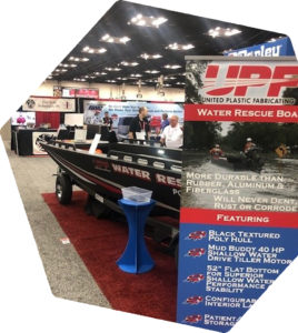
FDIC 2021 UPF Introduced the Water Rescue Boat with Poly Hull We have designed this boat to obtain optimal performance allowing you to get to

Joe Lingel Retires from UPF United Plastic Fabricating, Inc. (UPF) announces that as of September 1, 2021, Joe Lingel, CEO of United Plastic Fabricating, Inc.
MIFDI learns all about UPF Poly-Tank Design Just last week, United Plastic Fabricating hosted the Massachusetts Institute of Fire Department Instructors at our Massachusetts location.

UPF tanks and big OEMs at South Elgin open house for Fire Prevention Week! United Plastic Fabricating’s Pat Cahill had the wonderful opportunity to attend
This site uses functional cookies and external scripts to improve your experience.
Privacy settings
Privacy Settings
This site uses functional cookies and external scripts to improve your experience. Which cookies and scripts are used and how they impact your visit is specified on the left. You may change your settings at any time. Your choices will not impact your visit.
NOTE: These settings will only apply to the browser and device you are currently using.
Privacy Policy
We use cookies to make the UPF website a better experience. Cookies help to provide a more personalized experience and web analytics for us. Click here to view our Privacy Policy.